|
Seems like somebody forgot their thinking cap when
they let all the electrical goodies fire up before the
engine does (or maybe they just want to sell more
batteries). Suzy's seem to be a bit finicky with regard
to the amount of available juice to fire off a cold
engine. Couple that with the fact that batteries are at
less than optimum output when they are cold, and you got
the potential for a non-ride event.
Not to brag on the brains of a competitor, but Kawasaki
Vulcan does not let its lights come on until after the
starter button is released. Now on a scale for things
that make sense, I'd rank that one right at the top,
alongside the Valkarie's brake reservoir windows facing
the rider!!
Soooo...my big winter project for 2000 was to incorporate
a pull type brake light switch and relay(s) into the
kickstand mount which would control the lights, so that
when the stand is down, no juice will go to the headlight.
JC Whitney Relay Switch Pt# 14JE9433Y ($5.95) (get two
if you want to cut the tail & running lights)
Dennis Kirk Part no. 21-0119 Universal Brake Light Switch
$5.99.
(or Chrome Specialties Brake Light Switch, part no. 37054
available from your local Harley shop.)
Corrugated flexible electrical tubing (from AutoZone) $2.95
Bullet electrical connectors (from AutoZone) $1.79
Primary wire (already had that)
Total investment: Approximately $30.00 ($10 of which was
shipping costs)
Estimated return on investment: We won't even go there ;-)
The Black and Green wires are the "Working"
wires to the relay. Load the green one and ground the
black one (or vice versa) and the relay will click into
action. The Red, Yellow and White wires coming from the
relay are the "Duty" wires.
The Red wire is the primary load wire. It should be wired
hot.
The White wire goes hot when the relay is grounded (circuit
is closed).
The Yellow wire goes hot when the relay is not grounded (open
circuit).
Remove the Yellow wire from the relay plug, you won't be
needing it.
WHERE TO
INSTALL THE RELAYS:
|
Inside the headlight housing, you
will see two loop wires on the connector that
comes down from the right handlebar control.
These two loops are the lifelines to the
headlight, and the tail/running lights, and this
is the magic spot for the relay(s). (Using the
kickstand switch as a relay ground, you can
control two relays with the one switch, and cut
the tail/running lights as well as the headlight)
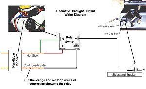
At the headlight/handlebar junction plug, cut the
Orange w/Red loop wire that connects the Orange
to the Yellow/White wire.
Connect the Orange side of the wire (the hot side)
to the Green and the Red wires that go into the
relay switch.
Connect the White wire from the relay to the
Yellow/White side of the loop wire (the cold side).
Run the Black wire (inside the corrugated conduit)
from the relay down the frame and under the
engine case on the left side, and run it all the
way back to the driveshaft.
If you wish to cut the tail/marker/speedo lights
and horn as well, wire a second relay into the
remaining loop on the plug in the same manner.
However, you will not need to run the black wire
to the Kickstand, you can just splice it into the
one from the other relay. |
Relay

Click the image for larger format
|
|

Click for larger format |
The relay that I used came with its
own connector and pigtail wires, therefore the colors of those
wires were described on this page and depicted in the diagram
above. If you purchase a relay with no wiring attached, you may
use any color wiring you wish as substitutes for what I have
shown.
To find the hot and cold sides of the loop wire, look at the
backside of the connector for the solid orange, and the yellow
and white stripped wires. The orange is hot with the ignition,
so the half of the loop directly on the other side of the
connector is your hot half.
|
THE FUN
PART: (THE SWITCH)
|
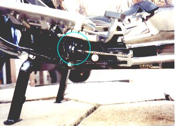
The pull switch will be mounted
to the inboard topside of the heavy steel plate
that supports the left driver footboard and
gearshift lever. Then it will be connected to the
kickstand by using a small nickel plated chain (hardware
store item). This chain will be used instead of
the usual spring wire, due to the length of
travel of the kickstand. This will allow you to
set the switch in the "on" position
with the kickstand up, then the chain simply sags
down when the stand is down, allowing the switch
to close.
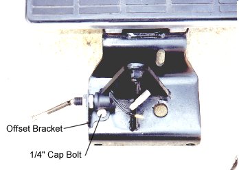
The pull switch will be mounted to the plate via
an offset corner bracket. (See mounted switch
photo.) You can simply drill a 1/4" hole
through the plate and bolt the bracket down.
Connect one switch wire to the Black wire from
the relay switch(es), and connect the other one
to a short section of wire, and ground it
somewhere nearby. |
Bracket

|
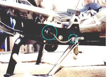
Drill a small hole into the solid part
of the kickstand just down from where it becomes a "U"
(This can be done without removing the kickstand). Secure
the chain to the kickstand by threading a cotter pin onto
a link in the chain, then through the hole you just
drilled. (Be sure to locate the hole and the cotter pin
so that it doesn't interfere with the operation of the
stand). Check to make sure that the chain does not pull
the plunger out to it's limit when the stand is up, then
snip off any excess chain. NOTE* The chain can
also be attached via a small cable tie if you prefer not
to drill into your stand.
Now, when the stand is down the circuit to the relay is
ungrounded, and the headlight/tail/running lights will
remain off. Lift the stand and on come the lights!!
| Switch Off 
|
Switch On 
|
Relays are hidden in the headlight housing. Switch
mechanism is neatly tucked under the floorboard, and
everything works automatically. Now the battery can
concentrate on the important stuff, like cranking a cold
engine, and recuperating during warm-up!!
A piece of heavy copper wire, or gem clip can be bent
to hold a loop in the chain, should you have a need to
park the bike with the lights on (Emergency or roadside
assistance, etc.)
In the event of any electrical component failure, all
connections were made with opposing bullet connectors,
which will allow instant "bypassing" of any
component used in this setup.
Optional
Setups for those less technically motivated
|
Although I prefer the more controllable configuration
above, many people do not feel that they need this much
control, or want to get this complex.
As a less expensive, less technical, and certainly less
effective alternative, a single relay can be wired from
the Yellow/Green Starter button wire to kill the light
just when the starter is engaged. Wire the relay to be
"Normally On", then use the starter tap wire to
cut the relay Off while the starter is engaged. While
this does nothing to reduce the ignition switch draw
down, nor does it aid in after-start recovery, it is
easier to install, and with virtually no concerns over
component failure.
|