|
Pair Valve (2nd Air)
System Removal - The Final Chapter!
Removing the Electronic
Solenoid from the Harness
For those who wish to
shed the entire system on their FI equipped C90, C50,
M50 models
THIS IS A DIY PROJECT AND REQUIRES
THE ABILITY TO SPLICE AND SOLDER WIRING
|
|
For the Boulevard Cruisers with Fuel Injection
systems, when you remove the pair valve (also known as "2nd Air" System)
from the bike, it is usually necessary to leave the small film canister
sized electronic solenoid attached to the bike's wiring harness in order
to avoid getting a fault reading during routine startup diagnostics
(engine light on). The reason for this is that the system will send a
signal to the solenoid to make sure it's there and working, and if it
isn't, you'll be notified with the check engine light. This last little
nagging part can be dealt with by replacing the solenoid with an inline
resistor, which will satisfy the diagnostics check.
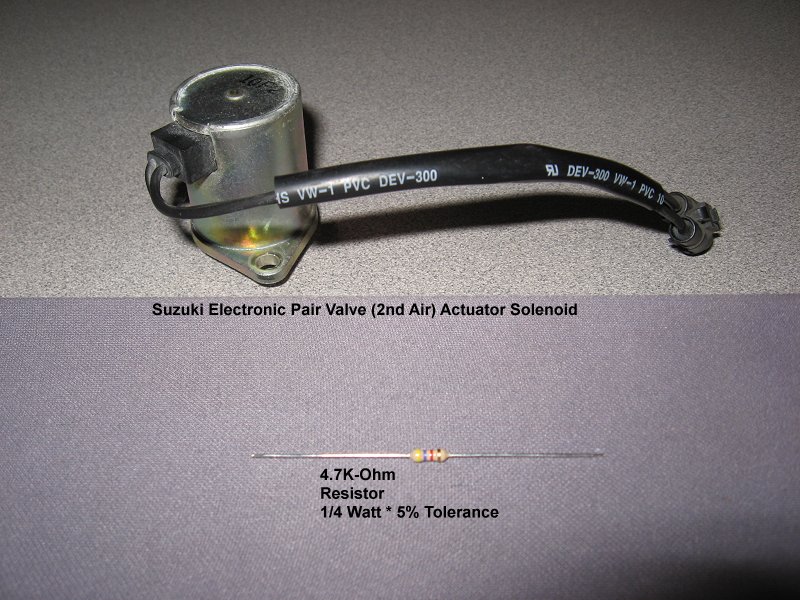
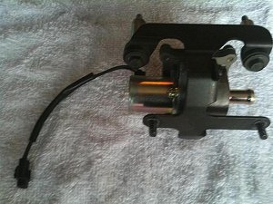
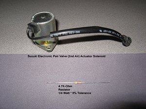
This is a complete pair valve
assembly, with solenoid still attached. Your bike's assembly may
look slightly different due to model variations, but the
solenoid (wired) part is essentially the same on all C90, C50,
and M50 bikes.
|
 |
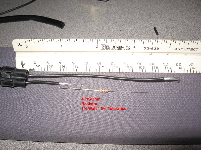
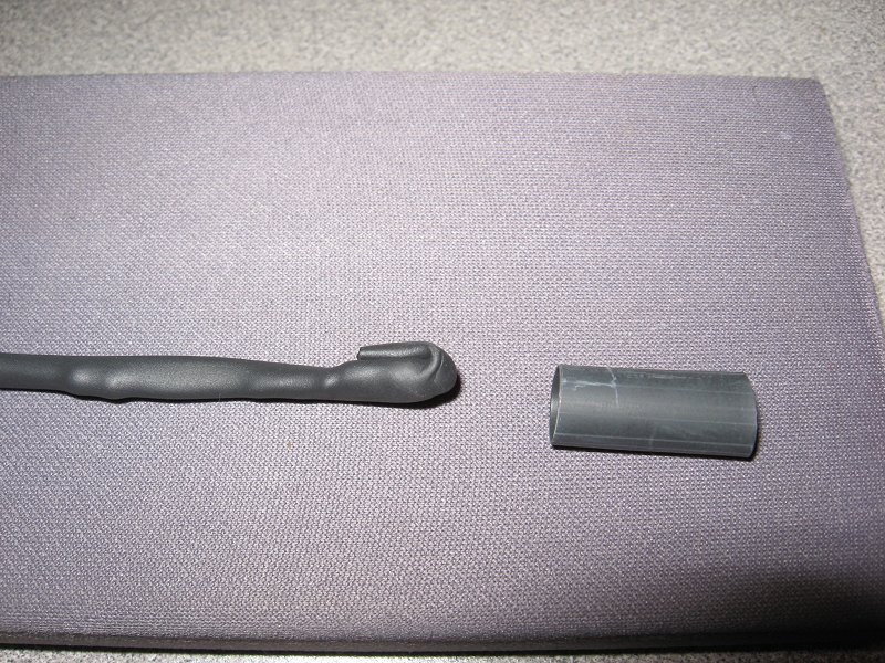
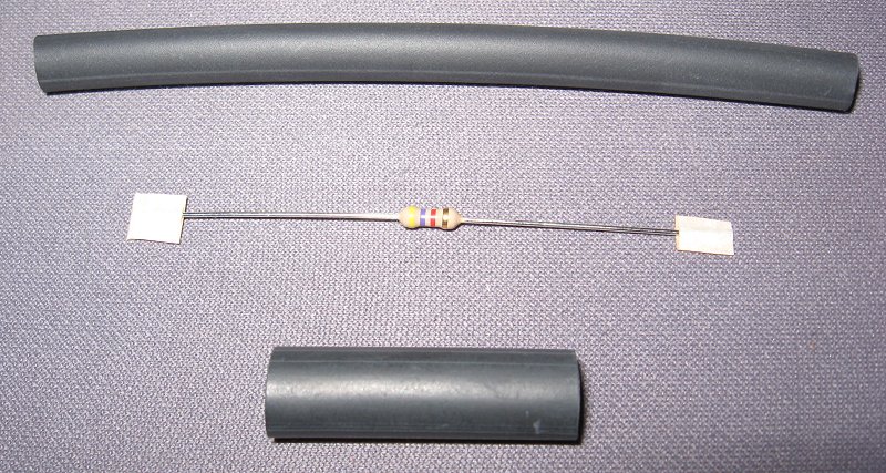
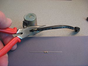
This is the solenoid after having been removed
from the pair valve assembly. Below it is a 4.7k-Ohm 1/4 Watt
inline resistor that we'll use to replace the solenoid on the
wiring harness.
These resistors are available from most any
electronics store, or you can order them in bulk through
Amazon
|
|
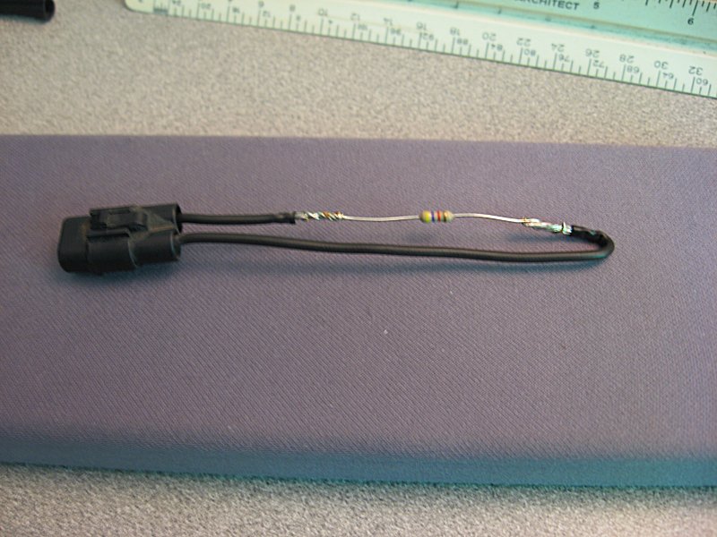
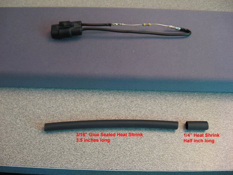
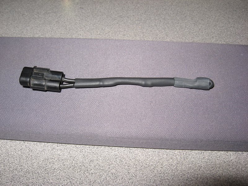
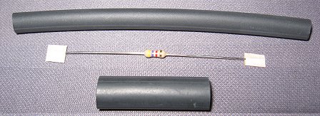
It will be necessary to cut the original pigtail
wire from the solenoid in order to solder in the resistor and
have a plug-n-play component. Although the solenoid COULD be put
back into service by splicing the original wires back together,
this should be considered a permanent change to the bike.
NOTICE!
That solenoid is a $180 part, so if you think there's ever
a chance you might want to put it back to original
configuration, STOP NOW and just plug the solenoid back into the
bike harness as per your pair removal instructions!
|
|
Please note: If at ANY TIME during the removal process, you
purposely or accidentally turn your ignition on, while that
connector is not in place, your bike will record a fault in the
system, and may continue to light the check engine light for up
to 50 start ups. To avoid this annoyance, remove the key from
the ignition before you ever start your project!
|
|
|
Many thanks to my cyber
friend Daniel "Redfire 05GT" from the Volusia Riders for
technical and component information for this project!
|
|